
Use the CLD Build toolbar to add variables, connectors and annotations to your model. This is a simplified version of the Model Build Toolbar that makes it easy to create Causal Loop Diagrams (see The CLD Window). It also includes some things from the Mode Toolbar.
Click this tool to create a variable. A variable in a causal loop diagram is a name that can then be connected to other variables. Names should be chosen so that it is clear what a value for the variable would mean. For example, "happiness," even though measurement might be tricky, has a clear meaning for more and less whereas "alternative futures" does not.
Click this tool to create a connector; select from the dropdown menu to choose from different connector types. A connector connects variables to each other.
Click this tool to create a stock; You can only connect flows into stocks.
Click this tool to create a flow; Flows can connect to stocks directly (by dragging the end of the flows). Connectors into and out of flows will also work.
Click this tool to add a module. Modules are self-contained diagrams that you can connect to other diagrams, though typically they do not share variables.
Click this tool to use the ghost tool. Use the ghost tool to create variable aliases. Variable aliases help you keep your diagrams tidy by letting you use the same variable in separate locations in your model. This helps keep connections neat, when a direct connection would cause arrows to cross.
Click this tool to add a text box, or use the dropdown to select a Loop Labels, or a Navigation Button (Model). Use text boxes to display text in your model. You can use text boxes to add labels, instructions, and explanatory text right on the model diagram. Use the Loop Label to identify and highlight feedback loops. Use the navigation button to quickly jump to a different part of the model.
Click this tool to add a graphics box. Graphics boxes give you the ability to use visual elements to organize and annotate your model. You can use a graphics box to frame part of the model. You can also add images or other graphics, like maps, floor plans, or mechanical drawings, and use them as backgrounds for parts of your model.
In edit mode you can move things around and all connector handles will be visible.
Explore mode will hide connector handles and also the panel at the right. You can select, but not move things in explore mode. Double clicking will return you to edit mode.
Will open the interface window on the current CLD. While CLD can't be run, you can create interfaces that allow people to explore structure.
You can zoom in and out using the commands on the Edit Menu or with the zoom control. To activate the zoom control, click on the displayed percentage (160%, above), and the Zoom control will open:
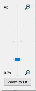
Drag the slider on the zoom control to the desired zoom, from 20% to 1200%. As you drag it, the current zoom will be displayed above it, and the model zoom will change.
Note If you have selected content then zooming will try to center the display on the selected content.
Note You can also use Ctrl++ to zoom in and Ctrl+- to zoom out (⌘++ and ⌘+- on the mac).