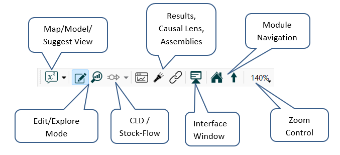
Use the Mode toolbar in the Model window to move between Edit and Explore mode, switch between Map, Mode, and Suggestl views, Navigate modules, and zoom in and out.

Click on the ![]() next to the icon to select which view you want to use.
next to the icon to select which view you want to use.
Use Map view
to lay out model diagrams and build models if you haven't yet, or even won't, add equations. The Properties panel will display only the Documentation
and Style
tabs. In addition, there will be no markers indicating validity placed on the model, and the dropdown on the Run toolbar displaying a list of errors or warnings won't be visible.
Use Model view
to work on the equations and the simulation characteristics of the model. The Properties panel will display the full set of tabs. Any invalid equations will be marked on the diagram and displayed in the Run toolbar.
Use Suggest View
to have suggestions for equations made whenever a new connection to a variable is added. This will also put a default equation of 100 for anything added to the model, and simulate the model as each change is made so you can see the current results. Invalid equations will be marked as they are in Model view and prevent simulation. See Suggest View.
Click this to switch to Edit mode, which will let you change the model, edit graphs, and otherwise edit. In Edit mode, the model isn't live, but graphs and tables will display results if they're available.
Click this to switch to Explore mode. Explore mode is intended to let you explore results. In this mode, the model is live, and available results are displayed in small graphs on top of each variable. Any change you make, by moving a dial or typing a value into the results panel, will make the model simulate again, and new results will be displayed.
Note: Running a model (from the menu or Run toolbar) switches it to Explore mode. Switching to Explore mode, on the other hand, doesn't run the model. Changing any constant value, through a knob, the Variable control panel, or the results panel, will, however, run the model, regardless of how you entered Explore mode.
Use this to switch between the stock and flow dialog used in editing, and the CLD Generation of the model structure. When the Loops Panel is open this will generate the CLD based on selected loops. Otherwise, it wil open the CLD Tag Selection dialog box.
Click to open the Results Panel. If no variable is selected (or multiple variables are selected) you will be asked to choose a variable to show results for.
Click to open the Causal Lens™. If no variable is selected (or multiple variables are selected) you will be asked to choose a variable to show the causes of.
This will open the Assemblies Panel to support model building with Assemblies. It is the same as the Open Assemblies Panel item on the Window Menu.
The module navigation buttons will be visible when you're working inside of a module. You enter a module by double-clicking on the module, or right-clicking and selecting Open Module from the dropdown menu. From within a module, use Show Parent Module ![]() to return to the parent of the module you're working in, or use Show Root Model
to return to the parent of the module you're working in, or use Show Root Model ![]() to return to the parent of all Modules (these may be the same). These navigation icons will disappear in the root module, and will never appear for models that don't use modules.
to return to the parent of all Modules (these may be the same). These navigation icons will disappear in the root module, and will never appear for models that don't use modules.
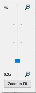
You can zoom in and out using the commands on the Edit Menu or with the zoom control. To activate the zoom control, click on the displayed percentage (160%, above), and the Zoom control will open:

Drag the slider on the zoom control to the desired zoom, from 20% to 1200%. As you drag it, the current zoom will be displayed above it, and the model zoom will change.
Note If you have selected content then zooming will try to center the display on the selected content.
Note You can also use Ctrl++ to zoom in and Ctrl+- to zoom out (⌘++ and ⌘+- on the mac).
Click on Zoom to Fit and the zoom will be set so that everything fits in the current window (it will zoom in or out, and adjust the scroll position, to make that happen).