CLDs do not have options to control simulation, so the only tab available is the Styles tab ![]() . Use it to set colors, fonts, and page size.
. Use it to set colors, fonts, and page size.

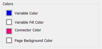
Variable Color is the color shown for all variables - stocks, flows, converters and modules, unless one of those types is explicitly overridden.
Variable Fill Color is the color that variable shapes will be filled with when they are drawn.
Connector Color is the color that connectors will be drawn.
Page Background Color is the color used for the background of the diagram. All objects, including variable names not in the center of stocks, will be drawn on top of this background.

Use this to set the default font for variables. Each of these can be overridden individually if desired.

Use this to set the default font for Text boxes and Loop Labels. You can overwrite the default values for any individual object.
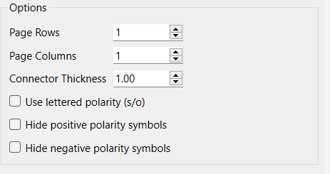
Use the Options to control the page size and connector appearance.

Page Rows, Page Columns - click the arrows or enter numbers to specify the size vertically (rows) and horizontally (columns).
Converter Thickness - click the arrows or enter numbers to specify the default thickness of connectors (you can override this for any individual connector).
Use lettered polarity(s/o) - if checked will display connector polarities using s (same) instead of + and o (opposite) instead of -.
Hide positive polarity symbols, if checked, will not display the + or s polarities. This is a common diagramming convention, and allows use of the polarity determination in the CLD Loops Panel without cluttering the diagram.
Hide negative polarity symbols, if checked, will not display the - or o polarities. This allows use of the polarity determination in the CLD Loops Panel without cluttering the diagram.